With all of the understandable attention devoted to powertrain components for pure battery and hybrid electric vehicles (BEVs and HEVs), it’s easy to overlook the fact that only about 3% of the cars sold in the U.S. in 2020 were non-internal combustion engine (ICE) vehicles (that figure is somewhat higher outside the U.S. and is expected to increase sharply in the next few years, with market forecasts spanning a wide range of predictions).
Nonetheless, regardless of the vehicle’s powertrain, nearly all now incorporate sophisticated infotainment systems to provide a combination of entertainment and information for a hopefully enhanced in-vehicle experience. These systems, of course, need significant amounts of power delivered via an efficient space-saving IC.
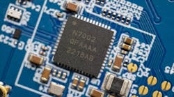
TheMAX25203fromAnalog Devicesis multi-phase synchronous boost controller that addresses these power requirements(Fig. 1). It enables infotainment systems to stay in regulation during cold crank or start-stop operation all the way down to battery input of 1.8 V after startup. The device also can be used to generate backlight voltage and Class-D audio-amplifier voltages.
Top Features
Among its features are programmable gate-drive voltage, current-limit blanking time, and accurate current balancing. The MAX25203 controller operates over a wide-ranging battery-input voltage spanning 4.5 to 42 V. Output voltage is adjustable to between 12 and 65 V while shutdown supply current is just 5 µA. The factory-programmable gate-drive voltage from 5.5 to 10 V increases power density by reducing MOSFET RDS(on)loss for higher efficiency and lower cost.
The MAX25203 operates at a resistor-set frequency of 220 kHz to 2.1 MHz, or it can be synchronized “on-the-fly” to an external clock. The higher end of the range enables use of small external components, reducing overall circuit-board footprint by 36% as well as the bill-of-materials (BOM) cost. The higher frequency also results in reduced output ripple and can eliminate AM band interference. In addition, the device supports spread-spectrum clock-frequency modulation to attenuate EMI in a given band.
The I2C bus diagnostics include provision for monitoring of die temperature and phase current, as well as optional true shutdown to improve system reliability. Output voltage is scalable via the pulse-width-modulation (PWM) input or I2C interface, and a sync-out feature supports operation with additional controller phases for higher-power systems.
The programmable current-limit blanking allows the device to handle high peak loads without need to oversize the inductor or overdesign the power supply, again allowing for a lower-cost solution. Efficiency is uniformly high as shown by the graphs on the datasheet(Fig. 2), and efficiency in pass-through mode when the supply voltage exceeds the output regulation voltage is above 98%.
Packaging and Eval Kit
The MAX25203 controller, housed in a 32-pin TQFN-EP package, is supported by a comprehensive 36-pagedatasheet. The companionMAX25203 Evaluation Kitis a fully assembled and tested board for assessing the performance and attributes of this dual-phase automotive synchronous boost controller. Its 18-pagedatasheetshows how to connect the board, use the GUI, and includes schematic diagram, BOM, and layout for the multilayer circuit board.