您将学到什么:
- 如何减少错误并统一MCAD和ECAD团队在同一设计上共同努力。
- How to design with high precision and enable MCAD and ECAD teams to work in their respective design environments.
- 如何帮助机械工程师执行详细的机械检查,有限元分析和修改放置,以确保满足机械约束。
对于许多电子产品,Flex和刚性板设计需要仔细建模弹性区域的机械行为,以确保满足形式的因素限制,并且挠性区域可靠。更快的产品释放循环加剧了这些问题,因此需要电气和机械工程师比以往任何时候都更加合作。
Success in these areas requires close collaboration between MCAD and ECAD domains to ensure mechanical constraints aren’t violated and the finalized design can be produced at scale. Because today’s design and data-management systems continue to lack basic integration features, collaboration between these domains still relies on file exchange between each side.
为了帮助设计团队克服这些生产力挑战,Altium开发了MCAD代码扩展程序。这个简单的实用程序将Altium Designer项目连接到通过Altium 365平台的流行MCAD应用程序。通过统一传统的MCAD/ECAD工作流程,多功能设计团队可以消除通常作为外壳设计的一部分,定义约束和干扰后检查的许多手动文件交换过程。
增强更有效的工作流程
One example of a unified MCAD/ECAD environment is Altium Designer with its CoDesigner panel. A matching add-on panel in MCAD software allows electrical and mechanical designers to interact seamlessly, enabling an efficient collaborative workflow.
Behind the scenes, this workflow is facilitated by server-side support, allowing design changes to be transferred, reviewed, and accepted or rejected without the need for manual file transfers in lossy file formats. The CoDesigner extension provides best-in-class model support by preserving references to board features, ensuring mechanical updates in one application are accurately reflected in the corresponding application.
在PCB布局工程师完成初始组件放置后,它成为机械工程师的工作,以检查所有内容是否适合围栏并根据需要进行通信所需的更改。在许多情况下,机械设计人员需要进行详细的机械检查,有限元分析(FEA)和修改放置,以确保满足机械约束。CodeSigner扩展程序启用了这些任务,还有更多用于具有同步和建模功能的PCB组件(请参见下面的视频)。
观看Quantel工程师使用Altium Designer进行ECAD和SOLIDWORKS的MCAD的动手演示,以优化和简化其机械和电气设计团队的方式,同时保持在自己熟悉的设计环境中。
设计数据同步
MCAD CodeSigner功能实现了一个简单的推杆进程,在该过程中,每一侧与CodeSigner面板中的一个按钮在两侧进行更新。一侧的更新可以在几秒钟内将其转移到同事,这会触发协作者的代码签名面板中的通知。每一侧都可以通过向每个推送操作添加注释来跟踪更改。
关键ECAD和MCAD数据的即时交换是可以完成的,而无需手动IDF/IDX/step/dxf文件导入和导出。两个域中的工程师都可以专注于设计,而不是创建和传输文件。
当将设计导入到MCAD应用程序中时,MCAD工具中所做的任何更改都与推杆功能同步回ECAD侧。一旦设计回到Altium Designer,PCB布局数据将立即更新,以反映板轮廓,铜,孔位置或组件位置的变化。
同样,随后的Altium Designer的更改可以推回MCAD侧,从而导致董事会模型在将设计恢复到MCAD应用程序中后进行更新。这种来回同步也应用于外壳,可以将其推入Altium Designer。
Precise Model Representation
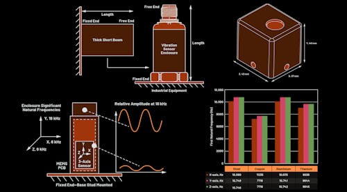
一旦将PCB组件进口到MCAD应用程序中,机械工程师就需要具有精确的板几何形状,并且在许多情况下,需要对铜和焊接面膜进行精确定义。该精确模型可用于执行详细的机械检查和诸如热分析之类的FEA。
同步MCAD和ECAD环境
CodeSigner扩展在MCAD应用程序中同步ECAD环境的许多重要方面,反之亦然:
- 机械设计师可以直接在MCAD应用程序中与PCBA模型一起使用。
- The mechanical designer can select and share elements of an enclosure back to the ECAD application, allowing the EE to see a model of the housing and any relevant constraints.
- Because the MCAD CoDesigner works with native MCAD data directly (and carefully), any mechanical constraints and dimensions defined among elements on the bare board, PCB components, or enclosure are preserved during each sync. In addition, since ECAD allows to lock components on the PCB, CoDesigner synchronizes ECAD’s “locked” state with MCAD’s “constrained” state.
- A standard method for enforcing mechanical constraints in an electrical design is to define a keepout region in the MCAD model. Because model references are preserved on each side, keepouts can be defined in the MCAD tool and synchronized back to the ECAD side.
同步约束
Altium Designer的本机3D设计工具在3D中提供了约束和间隙检查。可以将相同类型的清除定义和约束推入MCAD应用程序中,以用于机械设计任务。同样,有可能在MCAD应用程序中定义这些约束和间隙,并将其推回Altium Designer。这种同步水平有助于加快双方的干扰检查,并允许提早捕获干扰。
MCAD和ECAD组件链接
The CoDesigner extension automatically synchronizes components placed in the MCAD tool with corresponding components in the ECAD tool, and vice versa. This saves design collaboration time because the mechanical designer can immediately determine the appropriate location for mechanically constrained components, such as connectors and mounting holes. Placement in the MCAD application helps ensure enclosure constraints are satisfied—the mechanical designer will have full visibility of enclosure constraints, and the component definitions in the ECAD side are synchronized automatically.
在MCAD工具中,可以将保存定义为顶层或底层。这些保留分配将反映在PCB布局中,并检查是否对ECAD侧的设计规则进行了检查。如果需要,可以在Altium Designer中调整保留形状,并将其推回MCAD侧。
Bidirectional Support for Rigid-Flex Boards
Flex and rigid-flex assemblies require additional modeling and evaluation beyond what’s applied in rigid PCB assemblies. The MCAD CoDesigner extension provides support for flex and rigid-flex boards in both directions.
Rigid and flex regions, bending lines, and board shapes can be defined in the MCAD application and pushed back into Altium Designer. Once the layout engineer places components and completes initial routing, the design can be evaluated and previewed in the MCAD side alongside an enclosure. Bidirectional support for rigid-flex designs is seamless and follows the same workflow used for rigid PCBs.